Dr. Bryan Denov, S.T., M.T.
STEI-ITB
Dr. Ir. SyarifHidayat
STEI-ITB
Prof. Dr. Ir. Suwarno, M.T.
STEI-ITB
Prof. Reynaldo Zoro
STEI-ITB
Introduction
Observing lightning parameters is vital for minimizing strike risks. The four key factors are peak current, current steepness, charge, and impulse force. Notably, tropical and subtropical lightning has distinct characteristics. Designing an effective protection system requires considering local parameters. These form the foundation for safeguarding equipment and assessing potential impacts on nearby structures. Analyzing lightning damage and formulating protection strategies heavily relies on understanding lightning peak current.


The widely used methods for accurate direct lightning measurements include instrumented towers and triggered lightning. This paper introduces a novel method, the Peak Current Measurement System (PCM), applied in Indonesia, incorporating a Lightning Event Counter (LEC) and Magnetic Tape. The derived information aids decision-making for maintenance of lightning protection systems. By monitoring strike frequency and intensity through the LEC and processing data with Audacity software, authorities can gain insights into performance and vulnerabilities. This proactive approach ensures the safety and reliability of systems facing lightning-related hazards.

Calibration of Rogowski Coil
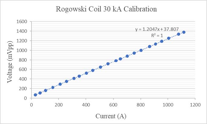
Impulse current with a waveform of 8/20 µs, in accordance with the IEC 62305/2010 standard, was injected into the conductor where the magnetic tape was installed. The purpose of this step was to calibrate the Rogowski coil measurement.

Application
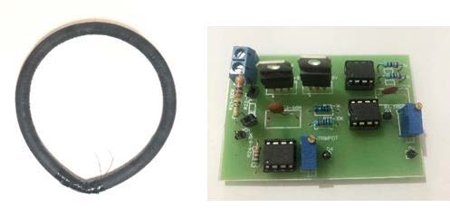
The Rogowski coil, a device designed to measure alternating current (AC) or high-speed current pulses, was evaluated as the input for a conditioning circuit.


To determine the overall accuracy of these coils, testing based on the IEC 61869-10 standard was conducted, focusing on current and phase errors. Both coils met the criteria for the 0.2 accuracy class, indicating that their measurement errors are within 0.2% of the actual value. This class is highly regarded for its precision, with only the 0.1 class being superior. An accuracy class below 1% is considered excellent for Rogowski coils, confirming that these coils are reliable for high-precision applications.


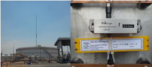
These installations encompass various types of constructions, such as freestanding masts, refinery facilities, transmission towers, tank storage areas, telecommunication towers, and tall buildings.
Furthermore, these measurement systems can be strategically positioned in areas characterized by a high frequency of lightning strikes.
Conclusions
From the results, Rogowski coils have been successfully manufactured with an accuracy class of 0.2 for current and phase error ratios, as per IEC 61869-10 standards, for measuring currents of 30 kA and 100 kA in telecommunication towers.